Our Principal Touch Panel Technologist and VP of Sales for Europe, Dr. Farouk Zabel, shared a 20-minute presentation on Low Reflectance Touch Panels during the electronic Displays 2017 conference in Germany. The video can be viewed below or on our YouTube page.
Video Transcript:
Good afternoon everybody! Today I would like to speak about the impact of adding discrete touch panels to a display system and how it affects the sunlight readability and ways how to minimize this impact.
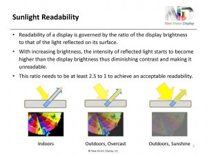
Sunlight readability is governed by the amount of light reflected on the surface of a display and touch panel system. The brighter the ambient light, the more light gets reflected on the surface of the touch panel and if the intensity of this reflected light exceeds or approaches the intensity of the light emitted by the display then the sunlight readability becomes worse and worse, examples are shown here. In general, it’s assumed that the ratio between the reflected light on the surface of a touch panel and the intensity of the display should be at least a ratio of 2.5 to 1. Military specs even require a 6 to 1 ratio to guarantee readability in bright sunshine.
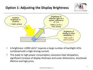
The easiest way, of course, to ensure that the display brightness is always brighter than the reflected light is to increase the display brightness to ensure that it is always higher. But if we look at how high the display brightness needs to be, then this becomes quite difficult. Ambient brightness on a bright day is around 7000 cd/m2 and this is probably a very conservative figure. Taking a touch display system with no treatment at all, with no measures taken to reduce the reflectance, we have a reflectivity of about 13% of that system which results in a reflected light intensity of above 900 cd/m2. To achieve this 2.5:1 ratio, the display brightness needs to exceed 2000 cd/m2. This is possible to achieve, but of course leads to very high power consumption, needs a lot of LEDs, high heat dissipation, the whole display becomes very thick, probably need to add a heat sink for that, the lifetime of the backlight of the display will be shortened and of course the price of this kind of display will be very high.
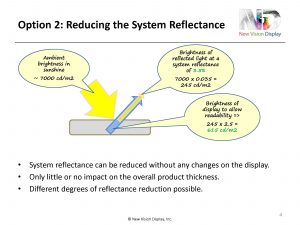
The 2nd option, of course, is instead of increasing the brightness of the display, to reduce the reflectance of the whole system. If you take the same conditions as before with 7000 cd/m2 of ambient light and a touch panel that has only 3.5% reflectance then we only need a display with a brightness of 615 cd/m2 which is significantly less and within the normal range of displays that are on the market. The advantages are definitely that for these touch displays, all changes can be done on the touch panel which in most cases are anyway customized; there is no impact or very little impact on the product thickness, price is much lower and also you can adjust to different degrees of reflectance according to the application where the display is used.
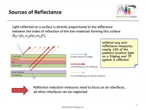
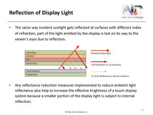
The total of the reflectances that occur on a touch panel and display when combined together originate from any interface where two materials meet which have different indices of refraction. This is expressed by the formula shown over there which applies to normally incident light only but for light incident at an angle it is different from this but for this purpose this approximation can be used. For an interface, for example between the ITO and the glass, the difference in the index of refraction between these two materials is very small, about 0.1, so the resulting reflection of the light, indicated here by the small thin orange arrow is also very small, only 0.1%, maybe a little more. But the main source of reflectance is actually on the air-to-glass interface or air to any other material such as ITO or adhesive, but typically it is a glass interface to air. For air, the index of refraction is 1, for glass it is 1.5, above 1.5 typically, which results in a reflectance of 4.5% on the air interface. So the total reflectance of a typical touch sensor consisting of a cover glass, adhesive, ITO layer, substrate glass and then mounted above a display has a reflectance of around 13%, so we have 4.5% reflection on each air-to-glass interface represented by the red arrow and adding this up you get, this is not added up but (using a special) formula it will be a little bit below 13%. So any measure taken to reduce the reflectance of a touch panel and display system we need to focus on these air interfaces, the other interfaces can be neglected. Even if you have a touch panel with, for example a GFF type of touch panel, two layers of ITO and two layers of adhesive, the contribution of these layers to the overall reflectance will be quite low.
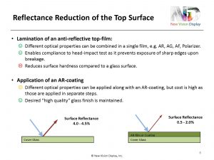
Obviously, the easiest thing is to reduce the reflectance of the top surface, which can be achieved in two ways. Either laminate a film on the top which has an anti-reflective property or apply certain coatings on the surface with AR properties. The advantages of using a film is that a film can also server other purposes. You can use film that combines AF and AR and AG (anti-glare). You don’t have only the AR as other optical properties might be desired, too, and especially for automotive applications, a top film helps to enable compliance to the head impact test which is actually required so that if the display breaks, in an accident for example, there are no sharp edges on the cover and when you have a film on top of the glass, this can be ensured. However, a film always reduces the surface hardness, it is difficult to get a film with a coating that has the same hardness as glass especially in combination with an anti-reflective surface. Application of AR-coatings is much better, it retains the high value of the glass and the touch performance that people look for in a touch sensor, but it is much more expensive, especially when the AR-coating is combined with other optical features and also when very low reflectance is required because an AR-coating needs to have more layers so that a better, lower reflectance can be achieved, but also this has a higher cost. Typically, with these measures, the reflectance can be reduced by about 2 to 3%, achieving 0.5 to 2% surface reflectance. This is only for the top.
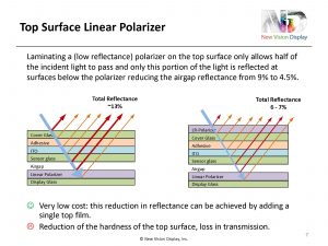
The next four options describe how to reduce the reflectance on the air gap, the two bottom red arrows shown here. The first option is to laminate a polarizer on the top surface which is a method that reduces actually the airgap reflection without even actually touching the air gap. The way it works is that with a polarizer on the top when the light that passes through it, only half of the light, depending on the polarizing direction only half of the light passes through, that means if only half of the light passes through, also only half of the light is reflected on every surface that is below this top polarizer. That means that the reflectance of the air gap which is originally about 9% or 8.5% is reduced to about only 4.5%. This is a very low cost solution that needs only one single film that is applied to the top but as stated before, any film on the top will reduce the feel and will reduce the hardness and also polarizers induce a loss in transmission that is undesired.
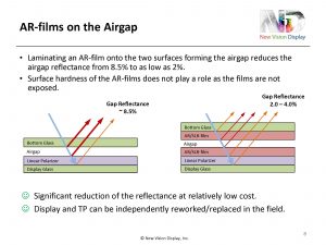
The second option to reduce the air gap reflection is to add AR-films, or SLR-films on the two interfaces of the air gap, one below the bottom glass of the sensor and one on the top of the display. This is quite effective, because it reduces the reflectance on that area from 9% to about 2%. The AR-films that can be used for this purpose are much cheaper than AR-films that have to be applied at the top because the hardness does not play a role as these films are never exposed to any touch, so they are not as expensive. With this solution, touch panels and displays can still be assembled with an air gap, which is easier for rework in the field, if either the display or the touch panel has to be repaired, it is easier to disassemble.
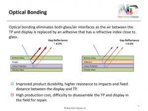
The most effective way of eliminating the reflectance of the air gap is optical bonding. I don’t want to spend too much time on this because the next three speakers will talk about the details of optical bonding and its advantages. Just to mention here that optical bonding is the most effective solution to reduce the reflectance; it is also the most expensive one or one of the most expensive ones and has the disadvantage that if one part breaks the whole unit has to replaced. But apart from improving the optical performance by reducing the reflectance and increasing sunlight readability, optical bonding also has the advantage of improving the durability, higher resistance to impact and also maintains the same gap between the display and touch panel which improves the performance of the touch.
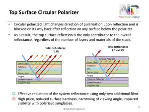
The last option is to laminate a circular polarizer instead of a linear polarizer on the top. A circular polarizer polarizes the light that passes through it and makes it circularly polarized and circularly polarized light when it becomes reflected on any surface, all of these arrows here, the direction of polarization turns by 180 degrees and then when the light comes back the circular polarizer will block this light because the polarization has been changed by the reflection. This is quite effective because it blocks all the light from coming through and if you combine the circular polarizer with an AR-film on the top you can reduce the total reflection of the whole system to 2%. The disadvantage of this method is that the price is high because you not only need to add the circular polarizer on the top but also need to add a ¼ lambda retarder on the top of the display to make sure that the display light that is also polarized still passes through that top circular polarizer. This method has been used in the past mainly for resistive touch panels used in military applications or in applications mainly used outdoors because in a resistive touch panel you have two air gaps; the air gap between the two ITO layers and another air gap between the touch sensor and the display. The reflectance of this system is very high, sunlight readability is bad and a circular polarizer may make a big difference to block all the reflections at all of these air gaps but for a capacitive touch panel this is not the ideal solution. Especially, also when you have a circular polarizer on the top the readability especially with polarized sunglasses can become quite difficult at certain angles.
All these methods I mentioned on how to reduce the touch panel and display reflectance not only reduce the reflectance of the ambient light shining on the display, but they also improve the transmission of the light coming from the display because less of the display light is reflected on the same surfaces that I talked about before. This means that also the more measures we apply for reducing the reflectance of the sunlight, we also increase the transmission of the touch panel and increase the brightness of the display light above the touch panel.
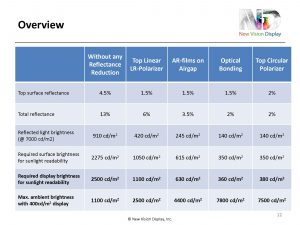
Putting this all together in an overview and comparing a display that has no reflection reduction measures at all, shown on the left column and [pointing to first row] assuming a top surface reflection with either an AR-film or an AR-coating or a polarizer that has AR features of 1.5%; for the top circular polarizer it probably can’t get that low of a reflectance. [Pointing to 2nd row] this shows the total reflectance of the system that can be achieved [pointing to 3rdrow] the reflected light brightness at an assumed ambient brightness of 7000cd/m2and eventually [pointing to bottom rows 5 and 6] this shows two different results; either the required display brightness that you need in order to make sure that sunlight readability is good at 7000cd/m2 and obviously the optical bonding method needs the lowest display brightness, 360cd/m2, all the others are significantly higher, or if you look at applications that need this kind of reduced reflectance for sunlight readability, you can also say: “OK, what is the maximum ambient brightness at which I can still read my 400cd/m2 display?” and also obviously it is optical bonding that allows the highest brightness outdoors for acceptable sunlight readability, but do all applications need actually be viewed at 7000cd/m2 ambient light? It is always the final application that governs what kind of highest brightness I need and also what kind of solution can I, or do I need to implement because cost is always, as far as I know, the biggest factor in choosing the final solution.
Source: https://goo.gl/6iK7TG
No comments:
Post a Comment