Showing posts with label Capacitive Touch Panel. Show all posts

Wednesday, 21 June 2017

Low Reflectance Touch Panels Presentation


Our Principal Touch Panel Technologist and VP of Sales for Europe, Dr. Farouk Zabel, shared a 20-minute presentation on Low Reflectance Touch Panels during the electronic Displays 2017 conference in Germany. The video can be viewed below or on our YouTube page
Video Transcript:
Good afternoon everybody! Today I would like to speak about the impact of adding discrete touch panels to a display system and how it affects the sunlight readability and ways how to minimize this impact.
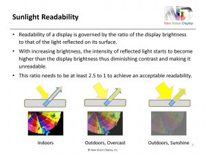
Sunlight readability is governed by the amount of light reflected on the surface of a display and touch panel system. The brighter the ambient light, the more light gets reflected on the surface of the touch panel and if the intensity of this reflected light exceeds or approaches the intensity of the light emitted by the display then the sunlight readability becomes worse and worse, examples are shown here. In general, it’s assumed that the ratio between the reflected light on the surface of a touch panel and the intensity of the display should be at least a ratio of 2.5 to 1. Military specs even require a 6 to 1 ratio to guarantee readability in bright sunshine.
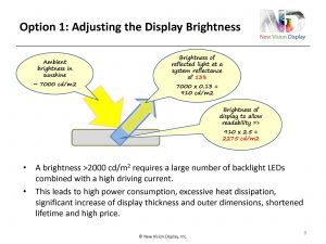
The easiest way, of course, to ensure that the display brightness is always brighter than the reflected light is to increase the display brightness to ensure that it is always higher. But if we look at how high the display brightness needs to be, then this becomes quite difficult. Ambient brightness on a bright day is around 7000 cd/m2 and this is probably a very conservative figure. Taking a touch display system with no treatment at all, with no measures taken to reduce the reflectance, we have a reflectivity of about 13% of that system which results in a reflected light intensity of above 900 cd/m2. To achieve this 2.5:1 ratio, the display brightness needs to exceed 2000 cd/m2. This is possible to achieve, but of course leads to very high power consumption, needs a lot of LEDs, high heat dissipation, the whole display becomes very thick, probably need to add a heat sink for that, the lifetime of the backlight of the display will be shortened and of course the price of this kind of display will be very high.
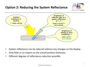
The 2nd option, of course, is instead of increasing the brightness of the display, to reduce the reflectance of the whole system. If you take the same conditions as before with 7000 cd/m2 of ambient light and a touch panel that has only 3.5% reflectance then we only need a display with a brightness of 615 cd/m2 which is significantly less and within the normal range of displays that are on the market. The advantages are definitely that for these touch displays, all changes can be done on the touch panel which in most cases are anyway customized; there is no impact or very little impact on the product thickness, price is much lower and also you can adjust to different degrees of reflectance according to the application where the display is used.
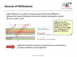
The total of the reflectances that occur on a touch panel and display when combined together originate from any interface where two materials meet which have different indices of refraction. This is expressed by the formula shown over there which applies to normally incident light only but for light incident at an angle it is different from this but for this purpose this approximation can be used. For an interface, for example between the ITO and the glass, the difference in the index of refraction between these two materials is very small, about 0.1, so the resulting reflection of the light, indicated here by the small thin orange arrow is also very small, only 0.1%, maybe a little more. But the main source of reflectance is actually on the air-to-glass interface or air to any other material such as ITO or adhesive, but typically it is a glass interface to air. For air, the index of refraction is 1, for glass it is 1.5, above 1.5 typically, which results in a reflectance of 4.5% on the air interface. So the total reflectance of a typical touch sensor consisting of a cover glass, adhesive, ITO layer, substrate glass and then mounted above a display has a reflectance of around 13%, so we have 4.5% reflection on each air-to-glass interface represented by the red arrow and adding this up you get, this is not added up but (using a special) formula it will be a little bit below 13%. So any measure taken to reduce the reflectance of a touch panel and display system we need to focus on these air interfaces, the other interfaces can be neglected. Even if you have a touch panel with, for example a GFF type of touch panel, two layers of ITO and two layers of adhesive, the contribution of these layers to the overall reflectance will be quite low.
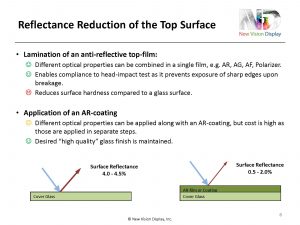
Obviously, the easiest thing is to reduce the reflectance of the top surface, which can be achieved in two ways. Either laminate a film on the top which has an anti-reflective property or apply certain coatings on the surface with AR properties. The advantages of using a film is that a film can also server other purposes. You can use film that combines AF and AR and AG (anti-glare). You don’t have only the AR as other optical properties might be desired, too, and especially for automotive applications, a top film helps to enable compliance to the head impact test which is actually required so that if the display breaks, in an accident for example, there are no sharp edges on the cover and when you have a film on top of the glass, this can be ensured. However, a film always reduces the surface hardness, it is difficult to get a film with a coating that has the same hardness as glass especially in combination with an anti-reflective surface. Application of AR-coatings is much better, it retains the high value of the glass and the touch performance that people look for in a touch sensor, but it is much more expensive, especially when the AR-coating is combined with other optical features and also when very low reflectance is required because an AR-coating needs to have more layers so that a better, lower reflectance can be achieved, but also this has a higher cost. Typically, with these measures, the reflectance can be reduced by about 2 to 3%, achieving 0.5 to 2% surface reflectance. This is only for the top.
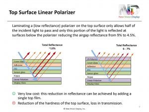
The next four options describe how to reduce the reflectance on the air gap, the two bottom red arrows shown here. The first option is to laminate a polarizer on the top surface which is a method that reduces actually the airgap reflection without even actually touching the air gap. The way it works is that with a polarizer on the top when the light that passes through it, only half of the light, depending on the polarizing direction only half of the light passes through, that means if only half of the light passes through, also only half of the light is reflected on every surface that is below this top polarizer. That means that the reflectance of the air gap which is originally about 9% or 8.5% is reduced to about only 4.5%. This is a very low cost solution that needs only one single film that is applied to the top but as stated before, any film on the top will reduce the feel and will reduce the hardness and also polarizers induce a loss in transmission that is undesired.
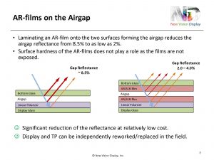
The second option to reduce the air gap reflection is to add AR-films, or SLR-films on the two interfaces of the air gap, one below the bottom glass of the sensor and one on the top of the display. This is quite effective, because it reduces the reflectance on that area from 9% to about 2%. The AR-films that can be used for this purpose are much cheaper than AR-films that have to be applied at the top because the hardness does not play a role as these films are never exposed to any touch, so they are not as expensive. With this solution, touch panels and displays can still be assembled with an air gap, which is easier for rework in the field, if either the display or the touch panel has to be repaired, it is easier to disassemble.
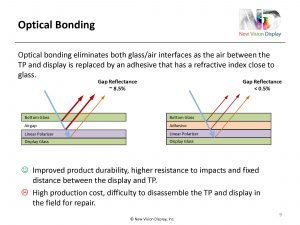
The most effective way of eliminating the reflectance of the air gap is optical bonding. I don’t want to spend too much time on this because the next three speakers will talk about the details of optical bonding and its advantages. Just to mention here that optical bonding is the most effective solution to reduce the reflectance; it is also the most expensive one or one of the most expensive ones and has the disadvantage that if one part breaks the whole unit has to replaced. But apart from improving the optical performance by reducing the reflectance and increasing sunlight readability, optical bonding also has the advantage of improving the durability, higher resistance to impact and also maintains the same gap between the display and touch panel which improves the performance of the touch.
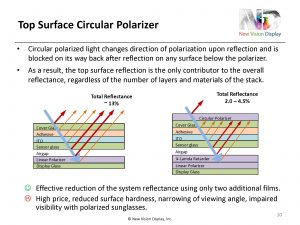
The last option is to laminate a circular polarizer instead of a linear polarizer on the top. A circular polarizer polarizes the light that passes through it and makes it circularly polarized and circularly polarized light when it becomes reflected on any surface, all of these arrows here, the direction of polarization turns by 180 degrees and then when the light comes back the circular polarizer will block this light because the polarization has been changed by the reflection. This is quite effective because it blocks all the light from coming through and if you combine the circular polarizer with an AR-film on the top you can reduce the total reflection of the whole system to 2%. The disadvantage of this method is that the price is high because you not only need to add the circular polarizer on the top but also need to add a ¼ lambda retarder on the top of the display to make sure that the display light that is also polarized still passes through that top circular polarizer. This method has been used in the past mainly for resistive touch panels used in military applications or in applications mainly used outdoors because in a resistive touch panel you have two air gaps; the air gap between the two ITO layers and another air gap between the touch sensor and the display. The reflectance of this system is very high, sunlight readability is bad and a circular polarizer may make a big difference to block all the reflections at all of these air gaps but for a capacitive touch panel this is not the ideal solution. Especially, also when you have a circular polarizer on the top the readability especially with polarized sunglasses can become quite difficult at certain angles.
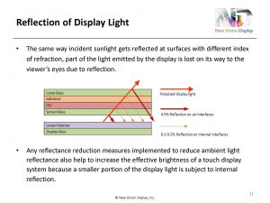
All these methods I mentioned on how to reduce the touch panel and display reflectance not only reduce the reflectance of the ambient light shining on the display, but they also improve the transmission of the light coming from the display because less of the display light is reflected on the same surfaces that I talked about before. This means that also the more measures we apply for reducing the reflectance of the sunlight, we also increase the transmission of the touch panel and increase the brightness of the display light above the touch panel.
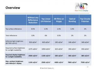
Putting this all together in an overview and comparing a display that has no reflection reduction measures at all, shown on the left column and [pointing to first row] assuming a top surface reflection with either an AR-film or an AR-coating or a polarizer that has AR features of 1.5%; for the top circular polarizer it probably can’t get that low of a reflectance. [Pointing to 2nd row] this shows the total reflectance of the system that can be achieved [pointing to 3rdrow] the reflected light brightness at an assumed ambient brightness of 7000cd/m2and eventually [pointing to bottom rows 5 and 6] this shows two different results; either the required display brightness that you need in order to make sure that sunlight readability is good at 7000cd/m2 and obviously the optical bonding method needs the lowest display brightness, 360cd/m2, all the others are significantly higher, or if you look at applications that need this kind of reduced reflectance for sunlight readability, you can also say: “OK, what is the maximum ambient brightness at which I can still read my 400cd/m2 display?” and also obviously it is optical bonding that allows the highest brightness outdoors for acceptable sunlight readability, but do all applications need actually be viewed at 7000cd/m2 ambient light? It is always the final application that governs what kind of highest brightness I need and also what kind of solution can I, or do I need to implement because cost is always, as far as I know, the biggest factor in choosing the final solution.

Tuesday, 16 May 2017

Displays for Medical Applications


Modern Medical Devices with Displays

Written by Frank Jammers, Field Applications Engineer (Europe) at New Vision Display, Inc.
Visualization is an important parameter in modern life and nowadays almost exclusively realized by use of Liquid Crystal Displays (LCDs). But not every LCD is equally suited for every application. Each and every employment has specific requirements that have to be met by the display of choice. Engineers, developers, and other decision-makers must have a deep and comprehensive understanding of how display specifications impact final products.

To choose the right display for a medical application, it’s important to know how a display differs from an industrial or consumer display, as well as the benefits realized by these specific features, and how they impact the application. To complicate matters, the medical market comprises of many sub-markets with requirements ranging from small, low-resolution panels (or even passive segmented displays) in rugged and mobile medical applications to large, high-resolution, high-contrast color or monochrome panels for medical diagnostics.


Tuesday, 29 November 2016

Elektrosil takes on exclusive distribution for New Vision Display in Germany, Austria and Switzerland

Elektrosil

After many years of successful collaboration, Hamburg-based Elektrosil is taking on the exclusive distribution for touch, display and cover glass products manufactured by production partner and display technology specialist, New Vision Display (NVD). The agreement was signed in July 2016 and is effective immediately in the Germany, Austria and Switzerland region (D-A-CH).

New Vision Display, with its headquarters in Roseville, California, employs more than 3,000 people worldwide and stands out with more than 30 successful years as an industrial supplier, not least as a Tier-1 manufacturer that expertise in custom display, capacitive touch panel, cover and ITO glass products. As a solutions partner, Elektrosil GmbH provides customised systems solutions in the field of electronic system components and electromechanical assemblies. On this basis, in close communication with customers and the manufacturer, the company develops made-to-measure concepts and solutions, in which consultation, engineering, design-in, production and technical support as well as storage options and logistics are always important parts of the overall workflow. Focus markets for both partners are the industrial electronics, automotive, medical engineering and smart home sectors as well as parts of the consumer sector.

The partnership between the two companies is immediately illustrated by shared locations. Wilfried Reeh, NVD, controls Business Development from the Elektrosil headquarters in Hamburg, and the control centre for the NVD sales department EMEA is located at the Elektrosil site in Nuremberg.
As a result of the intensified collaboration, Elektrosil GmbH offers an expanded product portfolio in the TFT and touch sector, and considerably greater flexibility in the associated software design; New Vision Display is continuing the successful expansion of the sales network. Both companies are confident of further strengthening their position on the European market as a result of the agreement.

Source: https://goo.gl/22GVCN

Wednesday, 23 November 2016

Designing Low Reflectance Touch Panels for Sunlight Readability

by Dr. Farouk Zabel, Principal Touch Panel Technologist & VP Strategic Business Development at New Vision Display, Inc.

Link to article on ECN Magazine’s Blog: https://www.ecnmag.com/article/2016/11/designing-low-reflectance-touch-panels-sunlight-readability

Placing a touch sensor on top of a display increases the overall reflectance of the device which directly influences the readability of the display in bright conditions, especially outdoors on a sunny day. This doesn’t only impact mobile devices that are often used outdoors, but also automotive displays, ATMs, marine applications, navigational devices and many more. This article outlines the relationship between the reflectance of a touch display system and its sunlight readability, and explains the parameters that influence the reflectance. Different methods of how reflectance can be reduced will be discussed and compared in terms of effectiveness and cost.

For a display to be readable in an environment with very bright ambient light, the brightness of the display (i.e. the intensity of the light emitted by the display) needs to exceed the intensity of the light that is reflected on the display surface. In other words, if the intensity of the reflected light is close to the display´s brightness, the contrast of the display is reduced to a degree where the display’s readability is diminished to unacceptable levels. If the total reflectance is higher, the display will not be readable at all. In order to maintain readability, the display brightness needs to exceed the reflected light by a factor of at least 2.5. Military specifications require a factor of at least 4, some even 6.

The ambient brightness on a clear day in direct sunlight is about 6000 cd/m2, and the typical reflectance of a display system including a touch sensor without any special measures for reflectance reduction is about 14%. This means that the light reflected on such a surface would be 6000 x 0.14 = 780 cd/m2. Typical consumer type displays with a brightness of around 350 cd/m2 would not be readable under those conditions.

One solution would be to boost up the display brightness to above 2000 cd/m2. Though possible in theory, this requires significantly more backlight LEDs (or other light sources) and/or a higher driving current, leading to high power consumption, excessive heat dissipation, increased dimensions and shortened lifetime. This is unacceptable for mobile devices, but even for fixed applications or displays used in cars, the display brightness is usually limited to 1000 cd/m2 for the above mentioned reasons.

An alternative way to make these displays sunlight-readable is to reduce their reflectance to a level that ensures that the intensity of the reflected light remains significantly lower than the display brightness. Reducing only the surface reflectance is not enough because the incident light is not only reflected on the surface. Underlying layers of different materials also contribute to the total reflection as light is also reflected at the interfaces of two different materials that have a different index of refraction. Therefore, adding a touch sensor to a display increases the total reflectance of the system.

As mentioned above, without any reflection reduction measures the total reflectance of the touch display system is about 14%. As shown in figure (1), such a system comprises three glass/air interfaces: The top surface of the cover lens, the bottom surface of the sensor and the top surface of the display, each contributing approximately 4.5% to the total reflectance. There are also a few internal interfaces, however, those do not add significantly to the total reflectance as the refractive index of the materials those layers consist of (glass, ITO, adhesive) are quite similar to each other. Thus, reflectance reduction measures mainly focus on the glass/air interfaces.
reflection of surface
                               Figure (1)

A.   The reflectance of the top surface can be reduced by either applying an AR-coating or laminating an AR-film, or any other type of film that has AR-properties and also serves an additional purpose (e.g. anti-glare, anti-smudge, anti-spall, polarization). The resulting top reflectance can be reduced to values between 1% and 2.5%, depending on the type of film used or, in case of AR-coatings, on the number of layers coated onto the surface. As one may expect, the lower the reflectance value of the film or coating the higher its cost.

B. The reflectance of the other two glass/air interfaces at the bottom of the sensor and on top of the display can be reduced by the four different methods outlined below. For easier comparability, the system reflectance values provided below are based on the assumption that no reflectance reduction measure is applied on the top surface.
  1. Optical bonding of the display and capacitive touch panel: This is achieved by filling the gap between the display and the sensor with a transparent adhesive. As a result, the two lower glass/air interfaces shown in figure (1) are eliminated which reduces the total reflectance to approximately 5%. Optical bonding, however, comes at a high price. It requires very specific types of liquid or film adhesives that are quite expensive, and the production yield of laminating two expensive components (the display and the touch sensor) contributes significantly to the total cost. For small to medium-sized displays (up to 12”), the estimated cost of optical bonding is about $1.00 per diagonal inch.
     
Article Source: https://goo.gl/jcekvx

Monday, 8 August 2016

Application of Single, Dual and Multi-Touch User Interfaces on Projected Capacitive Touch Screens

By Dr. Farouk Zabel, Principal Touch Panel Technologist and Vice President of Strategic Business Development for Europe at New Vision Display

One of the biggest advantages projected capacitive touchscreen technology has over other touch technologies (especially resistive touch) is the capability to support the recognition of two or more distinct touches. This is why many OEMs who designcapacitive touch sensors into their products,want to have this magical feature called “multi-touch”.

However, very few applications actually requirea user interface that supports true multi-touch. For example, I have been using a smart phone for years and I can’t remember a single instance when I needed more than two fingers to operate any feature or game on that phone. Even the two-finger operation is limited to the zoom function. Therefore, it’s important to consider the scope of the product’s UIwhen designing a projected capacitive touch sensor and defining its specification. This way, OEMs canavoid designing-in an expensive touch panel, when one at a lower cost would be fully sufficient.

Here is an overview of the capacitive touch panel designs used in varioususer interfaces, and their performance related to the number of touches and supported gestures. The designs are listed according to their cost starting from lowest to highest.

  1. Icon-Based User Interface:
This type of UI utilizes predefined touch areas distributed over the screen. Within these touch areas are icons that display on the screen, often in varying menu screens. Gestures such as swiping or scrolling are not supported. The corresponding sensorsonly require a single layer of ITO with a predefined button layout and a simple button-type controller with limited input pins depending on the number of buttons.

  1. Low-Resolution, Single-Touch,Gestures in One Direction Only:
With this type of UI, single touches can be sensed anywhere on the screen, not just on predefined areas. It’s suitable for devices which typically don’t display pictures that require a zoom feature, but still need single touch gesture support for scrolling or swiping. This type of interface is commonly found in industrial and household applications, remote controls, and consumer medical devices. Here, the sensor can also be realized by a single layer of ITO, typically employing a triangle or backgammon pattern.Reliable gesture recognition is supported by this pattern only in one direction, i.e. either vertically or horizontally. It requires a simple capacitive touch controller with the number of inputs depending on the screen size. Typically, these types of sensors are limited toapproximately 4” diagonal.

Capacitive TouchScreen

New Vision Display is a custom LCD, OLED display and capacitive touch screen manufacturer based out of Roseville, CA. For more information, please visit www.newvisiondisplay.com.

Article Source: https://goo.gl/BHDhdc

Thursday, 31 March 2016

Ways to Enhance the Functionality of LCD Displays

      Every day, we swipe, pinch or zoom; LCD displays are part of our daily lives. We’ve grown accustomed to using them on mobile devices like cell phones and tablets, when we withdraw money from ATM machines, as we’re loading addresses into navigation devices, and on the dashboard in our cars. Virtually every industry uses displays: Military, consumer, medical, automotive, industrial and marine. In order to perform such vastly different environments, displays require some sort of enhancement.

LCD Display
 
   An LCD enhancement can be anything from adding a simple resistive, capacitive touch panel to adding EMI/RFI conductive coatings. These enhancements are what enable the display to meet specific customer, industry, and environmental performance expectations. Let’s take a look at some of the many LCD enhancements.

  • Touch screen Integration: Adding a resistive or capacitive touch panel enables the display to be operated by touch.
  • Optical Films:Adding films such as anti-reflective(AR), anti-glare(AG),or heat-rejecting(IR) enhance a display’s visibility in bright or outdoor conditions.
  • Privacy Filters: A privacy filter prevents images on the display screen from being viewed from the side.
  • Vandal-Resistant Glass: This is commonly used on ATMs, parking meters, and digital signage.
  • EMI/RFIConductive Coatings: These protect the display from various types of atmospheric disturbance and are commonly used in medical applications.
  • LED Backlighting Enhancements: Existing LED backlights can be replaced with brighter and/or longer-lasting LEDs to improve performance.
  • Optical Bonding: By eliminating the air gap between the LCD and the other substrates, optical bonding enhances the display’s view-ability and ruggedness.
  • Heaters:Adding a heater to the LCD allows it to work in extreme cold temperatures.
  • Cover Lenses: Adding an additional layer of protective glass (i.e. Cover lens) reinforces the strength of the glass screen. Glass cover lenses can be made out of incredibly durable materials such as Corning® Gorilla® Glass.
      
 As you can see, many enhancements can be made to a LCD display so that it will meet the customer’s needs within their specific industry. No LCD can meet all the needs of every application. That’s why it’s important to know the requirements of your application and which types of displays and enhancements are available by your LCD Manufacturer during the design phase. With the right selection, your manufacturer can create the perfect LCD display module for your product.


Article Source: https://goo.gl/i8ZcGg